
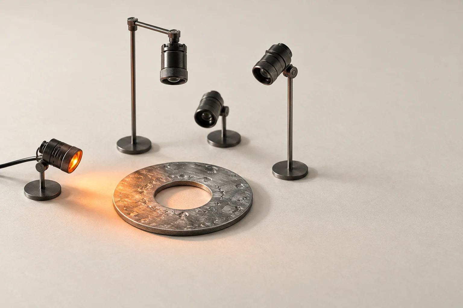
When an inspection project struggles, the first instinct is to blame the model. In our optics lab, the cause is far more often the light. A camera records light, not parts. If the illumination doesn’t make the defect look different from good material, no amount of training will find it reliably. If it does, even a simple model often will.
So we choose lighting before we choose anything else, and we choose it by asking how the defect interacts with light: does it change the surface angle, the reflectance, the transmission or the height? Below are the main geometries, polarization, wavelength and strobing, a table matching defects to lighting, and the routine we use to test samples.
Start with what the defect does to light
Every defect is visible only because it changes the light that reaches the sensor. Four questions cover most cases:
- Does it change the surface angle? Scratches, dents, wrinkles, embossing and cracks tilt small areas of the surface and redirect reflected light.
- Does it change reflectance or color? Stains, burns, discoloration and print errors absorb or reflect different wavelengths.
- Does it change transmission? Holes, voids, inclusions in film or glass, and fill levels change how much light passes through.
- Does it change height? Warp, missing components, bead volume and coplanarity are three-dimensional and often need a height measurement.
Then look at the surface. A specular surface (polished metal, glass, glossy film) reflects light like a mirror, at one angle. A diffuse surface (paper, matte plastic, cast metal) scatters it in all directions. The same light can be perfect on one and useless on the other.
Bright field and dark field
The most important geometric idea in machine vision lighting is whether the camera sees the mirror reflection of the light source or not.
In bright field, the light is placed so that its reflection from a flat surface enters the lens. Flat, good material looks bright; anything that tilts the surface, such as a scratch or a pit, reflects light away and appears dark.
In dark field, the light arrives at a low angle so that its reflection misses the lens. Flat material looks dark, while edges, scratches, particles and raised features scatter some light toward the camera and appear bright against a dark background. Dark field is often the best way to see fine surface defects on smooth parts.
Low-angle and raking light
A low-angle ring or bar light, often 10 to 30 degrees above the surface, is the workhorse of dark field. A single bar from one side, called raking light, exaggerates relief along one direction, which makes it excellent for embossing, seal wrinkles and texture. It is also directional: a scratch running parallel to the light can almost vanish. For defects that appear in any orientation, use a full ring, or a segmented ring that fires one quadrant at a time and captures an image per segment.
Diffuse dome
A dome light bounces illumination off a white hemisphere so it arrives from nearly every direction, like an overcast sky. Glare on curved, shiny parts disappears, which makes domes ideal for print on foil, labels on bottles and color on glossy surfaces. The trade-off is that a dome also suppresses relief, so the shallow dent you need to find may disappear along with the glare. Domes have to sit close to the part, and the camera hole at the top shows up as a dark spot on flat, mirror-like parts.
Coaxial
A coaxial light sends illumination along the camera’s optical axis through a beam splitter. Flat specular surfaces reflect it straight back and look evenly bright; anything angled, such as scratches, pits or laser-marked characters on metal, appears dark. It is the right tool for flat, polished parts and a poor one for curved ones. Because the light passes through the beam splitter twice, a 50/50 splitter delivers at most a quarter of the source light to the sensor, so budget for a stronger source.
Backlight
With the light behind the part, the camera sees a silhouette. Backlighting is the simplest route to dimensions, holes, presence or absence of features, and fill levels in translucent containers. A diffuse backlight is fine for presence checks. For precise edge measurement on thick parts, a collimated backlight paired with a telecentric lens avoids the soft, ambiguous edges that diffuse light creates.
Structured light
When the defect is a height difference, project a known pattern and measure how the part distorts it. Laser-line triangulation builds a height profile as the part moves under the line; projected fringe patterns capture a whole area at once. Use structured light for bead volume, warp, missing components and coplanarity.
Polarization
Specular reflection largely preserves the polarization of incoming light, while diffuse scattering largely scrambles it. Put a linear polarizer on the light and a second one on the lens, rotated 90 degrees, and most of the specular glare is blocked while the diffuse image remains. This cross-polarization is how you read a label through shrink film or inspect a glossy molded part without hot spots.
Crossed polarizers on a backlight also reveal internal stress in transparent plastics and glass, which shows up as bright or colored bands. The cost is light: each polarizer passes less than half of unpolarized light, so plan on several times the source power of an unpolarized setup.
Choose the wavelength deliberately
With a monochrome camera, the usual choice for inspection, wavelength is a contrast control.
- Red (around 620–660 nm): efficient, inexpensive LEDs and good sensor sensitivity. A bandpass filter matched to the LED rejects much of the ambient light.
- Near-infrared (850 nm and 940 nm): many dyes and color inks become nearly transparent, so print can disappear and you see the substrate beneath it, while carbon-based black inks generally stay dark. Silicon sensors are less sensitive here, especially at 940 nm.
- Blue (around 450–470 nm): shorter wavelengths scatter more at the surface and penetrate less into plastics and fabrics, which helps with fine surface texture and scratches.
- Ultraviolet (around 365 nm): used to make materials fluoresce. Many adhesives, coatings and lubricants fluoresce naturally or can carry a fluorescent tracer, so their presence becomes a bright feature. UV needs proper shielding to protect people.
For colored features, a rule of thumb: light of the same color makes a feature bright, and the complementary color makes it dark. Under red light, a red mark on white looks nearly white, and a green mark looks nearly black.
Strobing versus ambient light
On a moving line, the strobe sets the effective exposure. A worked example: a conveyor runs at 1 m/s and each pixel covers 0.1 mm of the part. The part moves 0.1 mm in 100 µs, so a strobe pulse of 100 µs or less keeps motion blur under one pixel.
Short pulses also let you overdrive LEDs at high peak current and low duty cycle, so the strobe overpowers ambient light during the exposure. That is why our Lensnode V carries its own programmable strobe ring in white, red and 850 nm IR. Combined with a bandpass filter, a well-designed strobe makes the image almost independent of skylights, forklift headlights and overhead fixtures. Fixtures on 60 Hz mains can flicker at 120 Hz and beat against the frame rate, and uncontrolled ambient light is a major cause of slow model decay, as described in why your inspection model got worse in July.
Matching defects to lighting
| Defect | First lighting to try | Why it works | Watch for |
|---|---|---|---|
| Fine scratches on polished metal | Low-angle dark-field ring | Scratches scatter light into the lens against a dark background | Directional scratches; use a full or segmented ring |
| Scratches or pits on flat polished parts | Coaxial | Tilted areas reflect light away and turn dark | Needs a flat part; loses most of the source light |
| Dents and waviness on glossy panels | Structured light or a reflected stripe pattern | Slope changes bend the reflected pattern | Needs space and careful calibration |
| Seal wrinkles and channels on pouches | Low-angle raking light, often red | Relief casts shadows and highlights | Wrinkle orientation relative to the light |
| Print and labels on foil or curved shiny packs | Diffuse dome | Removes hot spots | Hides shallow dents |
| Glare through shrink film or glossy labels | Cross-polarization | Blocks specular reflection | Needs much more light |
| Holes, dimensions, missing features | Backlight, collimated for measurement | Silhouette gives maximum edge contrast | Translucent parts leak light |
| Fill level in translucent containers | Backlight; test NIR for dark liquids | Liquid transmits differently from air | Foam and condensation |
| Adhesive or coating presence | UV fluorescence | Material glows while the substrate stays dark | Needs a tracer if it doesn’t fluoresce |
| Warp, bead volume, coplanarity | Laser-line triangulation | Measures height directly | Speckle and occlusion |
| Stains and discoloration on matte parts | Diffuse bright field at a chosen wavelength | Even light isolates reflectance changes | Lot-to-lot color variation |
How we test samples
In a Feasibility Sprint, samples arrive in the optics lab and go through the same routine before any model is trained:
- Gather limit samples. Good parts, worst-acceptable parts, and each defect at the smallest size that must be rejected, labeled and kept as references. Our guide to writing an inspection spec explains why these matter.
- Fix the optics first. Set working distance, field of view and resolution so the smallest defect spans at least three to four pixels. Lighting can’t recover resolution the camera never captured.
- Run a lighting matrix. Image every sample under each candidate geometry, wavelength and polarizer setting, setting exposure by the same rule each time. Rotate parts through 0, 90, 180 and 270 degrees to expose directional effects.
- Measure contrast instead of eyeballing it. For each setup, compare the defect region with the surrounding good material relative to image noise, a simple contrast-to-noise ratio, and rank the setups.
- Check the good parts. Mold lines, grain, tool marks and print can light up under the same setup that reveals the defect. A light that makes good parts look defective just moves the problem into false rejects.
- Stress the winner. Shift and tilt parts by the presentation tolerance you expect on the line, try material from different lots, and switch the room lights on and off.
- Write the recipe down. Geometry, angles, distances, wavelength, filter, polarizer orientation, pulse width and gain, with a reference image to compare against when the system drifts later.
Light first, model second
AI tolerates variation that rule-based vision can’t, but it cannot recover information the image doesn’t contain. A good lighting design makes the defect the most obvious thing in the frame and keeps the image stable across shifts and seasons. That is most of the work. When off-the-shelf lights and cameras can’t get there, custom optical sensor design is the next step. For a complete cell, from optics to reject gate, see AI visual inspection systems.